Hartford sits on a complex glacial stratigraphy that makes retaining wall design anything but routine. The city's subsurface alternates between dense basal till, varved lake clays from Glacial Lake Hitchcock, and loose alluvial sands along the Connecticut River floodplain. A wall that works perfectly in the West End may fail near Keney Park if the designer assumes uniform soil. Our laboratory runs full ASTM D2487 classification on every project before a single dimension is drawn, because the difference between a silty sand and a lean clay changes the active earth pressure coefficient by 20 to 30 percent. When the Connecticut River rises during spring melt, pore pressures behind existing walls spike and we see failures that trace back to missing drainage provisions. The in-situ permeability testing we perform on these varved deposits gives us the real hydraulic conductivity numbers that textbook correlations miss entirely.
A retaining wall designed without site-specific friction angle data is a retaining wall designed to lean within three freeze-thaw cycles.
Our approach and scope
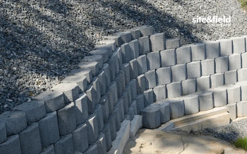
In Hartford we frequently encounter brownstone demolition debris mixed into the upper five feet of fill, a legacy of 19th-century construction that complicates bearing capacity checks beneath wall footings. The material looks like soil but behaves like poorly graded aggregate with sudden collapse potential when saturated. We run modified Proctor tests on site-specific fill blends to verify compaction curves before recommending a wall type. For cantilever walls in the downtown zone, where the IBC classifies the site as Seismic Design Category B, we model the reinforced concrete stem for overturning and sliding using ASDIP Retain with site-specific gamma and phi values from our triaxial lab. Gravity walls in residential areas near Elizabeth Park often use segmental block systems, and we specify the geogrid length based on the friction angle we measure directly rather than assuming a conservative 28 degrees. Deep excavation support near the viaduct sometimes calls for soldier pile and lagging walls, and our lab verifies the grout strength development curve before the tieback stressing sequence begins.
Site-specific factors
The direct shear machine runs a consolidated-drained test over 48 to 72 hours per specimen, and the technician checks the horizontal displacement transducer every 15 minutes against the log sheet. If the proving ring dial needle jumps backward, the soil has hit peak strength and started to soften, and that peak friction angle is the number the wall design needs. We run three normal stresses per sample, usually 200, 400, and 800 psf for shallow walls, and plot the Mohr-Coulomb envelope by hand before the software regression. A common problem in Hartford is that the varved clay samples extrude water during consolidation and the shear box leaks slurry onto the bench; the technician catches this early and aborts the test to repack the O-rings. The biggest design risk we flag in reports is assuming drained parameters for a silt that drains slowly enough to develop excess pore pressure behind the wall during a summer thunderstorm.
Quick answers
What soil parameters do you need to design a retaining wall for a Hartford residential lot?
We need the effective friction angle and cohesion intercept from a direct shear or triaxial test on an undisturbed sample, the moist unit weight from a Shelby tube, and a grain-size curve per ASTM D2487 to classify the material. For walls over six feet we also run a consolidation test if varved clays are present, because the preconsolidation pressure tells us whether the soil will compress under the wall footing or behave as overconsolidated.
How do you account for seismic loads on retaining walls per Connecticut code?
The Connecticut State Building Code adopts IBC 2021, which references ASCE 7-22 for seismic design. We apply the Mononobe-Okabe pseudo-static method with the peak ground acceleration from the USGS hazard maps for the site's coordinates. For Hartford, the mapped PGA at 2% in 50 years typically falls between 0.08g and 0.12g depending on the specific neighborhood. The active earth pressure coefficient increases, and we check the wall for additional inertial forces on the stem.
What does retaining wall design cost for a typical Hartford project?
The engineering fee for a retaining wall design package, including laboratory shear strength testing on one sample, wall calculations per IBC, and a sealed report, ranges from US$930 for a straightforward gravity wall under four feet to US$3,610 for a cantilever or MSE wall over eight feet with global stability analysis. Projects requiring multiple borings or tieback design fall at the upper end of that range.
Do you design both permanent and temporary retaining walls?
Yes, we design permanent walls for residential and commercial sites with 75-year service life assumptions, as well as temporary excavation support for construction-phase shoring. Temporary walls use the same soil parameters but different safety factors per OSHA excavation standards and often incorporate soldier piles with timber lagging rather than permanent concrete facing.